General Description
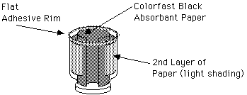
A sketch of our low-tech cloud chamber is shown here. Click the image to see a large figure. The chamber consists of an upside down plastic jar (#1 type plastic) with a metal lid. The metal lid becomes the floor of the chamber. The jar is cut horizontally. Adhesive is applied to the cut edge to make a flat surface on which a cover can be placed to seal the chamber. The transparent cover can be a plate of glass or clear plastic of a type that is not degraded by alcohol. Colorfast black absorbent paper lines the floor and sides of the jar, with an open space on the side for the light source. A small Styrofoam cooler cut to appropriate size contains the dry ice for cooling the base of the chamber. The metal lid of the chamber nests in a hole in the lid of the cooler, which rests, upside down, on its base.
Methanol or ethanol wets the blotting paper. A temperature difference is maintained by having only the bottom of the chamber on dry ice, so that the alcohol evaporates in the warm, top end of the chamber and condenses on air molecules ionized by radiation in lower cold half of the chamber.
Materials
| SUPPLIES | SOURCES | OUR COST |
|---|---|---|
| Plastic jar w/ lg. dia. metal lid | (large Clausen Pickle jar) | --- |
| Flat cover, glass or PETG* | *Laird Plastics, Seattle | $2.00 |
| Silicone 'aquarium' adhesive | Eagle Hardware | $3.00 |
| Black colorfast absorbent paper (Arches 100% cotton) | Daniel & Smith Art Supplies | $4.00 |
| Small Styrofoam cooler | Safeway | $2.50 |
| Solid CO2 (dry ice) (~ 2 lbs. per use) | QFC | $2.00 |
| Methanol or ethanol (~ 1 oz per use) | All World Scientific, Seattle | $1.00 |
| Light source (200 - 300 W) | (school supplied) | --- |
| Thermometer (optional) | (school supplied) | --- |
| Radioactive sources (optional) | Spectrum Techniques, Oakridge, Tennessee (school supplied) | --- |
| Radiation monitor (optional) | (school supplied) | --- |
Material Notes:
- Jar – We used a large Clausen Pickle jar. The lid diameter is 10 cm (4 in). The jar diameter is 12.75 cm (5 in). The jar is made of PETE, a No. 1 type of plastic, which is not degraded by alcohol.
- Flat cover – We chose PETG (also a No. 1 plastic) for the cover because it is available in clear sheet stock. A thickness of 1/8 or 3/16 inch would be adequate, but ours is 1/4 inch thick because it was available for $2.00 as a scrap piece. The cover was cut to 15 cm (6 in) square, large enough to cover our jar. A hole was drilled in an extra cover to accommodate a thermometer. Plexiglas (acrylic) is more commonly available, but it reacts with alcohol and becomes cloudy over time.
- Styrofoam – A small “double 6-pack” Styrofoam cooler works to hold dry ice. Dimensions at the bottom are about 15 cm (6 in) by 22 cm (9in).
- Dry Ice (solid carbon dioxide, CO2) – CAUTION! Dry ice (temperature of -78 C) must be handled with gloves.
- Alcohol – Methanol (CH2OH) and Ethanol (C2H5OH), 95% pure or better, both worked in the temperature range of our chamber. Rubbing alcohol (70% isopropanol) was not successful.
- Thermometer – A thermometer is helpful to monitor temperature in the chamber.
- Radioactive sources – These are listed as optional, because tracks of naturally occurring radiation (cosmic rays and radioactive decay of natural substances on earth) can be seen in the chamber. Because natural radiation occurs randomly, however, it may be difficult to know when the cloud chamber is working.
The radioactive sources used in our development work were:
| Isotope | Symbol | Decay Rate* | Half life | |
|---|---|---|---|---|
| alpha particle | Polonium-210 210 | Po | 0.1 curie | 38 days |
| beta particle | Strontium-90 | Sr | 0.1 curie | 28.6 years |
| gamma ray | Cobalt-60 | Co | 1.0 curie | 5.27 years |
*A curie is a unit measure of radioactivity equal to 37 billion disintegrations per second.
CAUTION!
Prolonged exposure to even low levels of radiation can be harmful. Minimize exposure to radiation by use of safe sources and appropriate shielding. See Radiation Safety for information on penetration of different types of radiation and appropriate shielding.
Only alpha and beta emitters are used in our demonstrations for the public.
Construction
A. Cut the plastic jar 7 to 10 cm from the metal lid. The plane of the cut should be parallel to the flat surface of the lid. This distance will be the height of the chamber. Apply a silicone adhesive to the cut edge of the jar and place this coated edge on wax paper on a flat surface to cure (dry). When the adhesive is cured, gently remove the wax paper.
B. Cut a circle of colorfast black absorbent paper to line inside of the metal lid, and a strip to line the side of the jar. Leave a narrow slot about 2.5 cm (1 inch) on the side for the light source. We actually lined the side of our jar with two strips. The first was equal in height to the height of the chamber, and the length matched the circumference of the lid, minus the space for the light. Our jar diameter however was larger and necked down sharply to the lid. We placed a second strip less wide (high), but longer to line the outside of the jar above its neck, thinking that this might increase the reservoir of alcohol in the top of the chamber, and thus improve the condensation results.
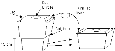
C. Cut the Styrofoam cooler to a height of about 15 cm (6 in). The “double 6-pack” cooler we used was trimmed at the transition between the smaller lower portion of the chamber and the larger upper section.
Cut a circular hole in the center of the lid of the cooler to match the diameter of the metal lid of your jar, so that the lid will nest in this hole. The Styrofoam lid should fit upside down on the trimmed lower portion of the Styrofoam cooler. The lid and rim of the cooler may need to have a 2.5 cm (1 inch) wide cut on a side to allow the light beam to enter at a low angle.
D. Cut Styrofoam blocks to place inside of the cooler to hold the dry ice in position under the lid of the jar.
Assembly
1. Wearing gloves, trim the dry ice to fit in the cooler. Scoring the ice with a saw blade will help achieve clean breaks at desired locations. Place the ice in the cooler with a flat surface up.
2. Place the cooler lid over the ice, upside down. The surface of the jar’s metal lid should contact the ice, when nested in the hole in the center of the upside down foam cooler lid.
3. Position the blotting paper in the jar as shown under item B above. Add enough methanol or ethanol to wet all the paper, but not so much that it pools in the bottom of the chamber.
4. Place the clear flat cover on top of the chamber, and shim under the cooler to level the floor of the chamber.
5. Position the light source so that it enters the chamber at a low angle downward through the gap in paper on the side of the jar.
6. Now turn down the room lights and look for cloud tracks of naturally occurring radiation.
If a known radioactive sample is used, place it to one side on the floor of the chamber between Steps 3 and 4 above. Position the sample so that the primary direction of emissions is horizontal across the floor of the chamber and is perpendicular to the light beam direction.
If you are having trouble seeing tracks, check the trouble shooting tips below.
Trouble Shooting Tips
If no paths are visible:
- Check for adequate alcohol in chamber.
The blotting paper should be wet with alcohol, but alcohol should not be pooled in bottom of chamber. If the chamber is opened periodically, alcohol vapor can escape and may need to be replenished. Check temperature gradient.
If the entire chamber is too cold, not enough alcohol will vaporize at top of chamber. Warm top of chamber, e.g., with hands over exterior surface, or by turning cover plate over.The bottom of chamber needs to be cold enough. In our experiments, we got clouds to form when the bottom of the chamber was below -15oF. - Check that bottom surface of the chamber is level.
If it is not level, convection currents may interfere with the cloud paths. If the ice on which the metal lid rests is not level, the Styrofoam cooler may be shimmed from the outside to make it level. - Check lighting.
A shallow angle from horizontal seems to work best for the angle of illumination. Adjusting the beam so that its reflection off the blotting paper is not directly behind the location of expected paths, relative to line of sight, may help. Adjusting the viewing angle may help too. Also check that ambient light is dim or absent. - Apply an electrostatic charge to the cover plate of the chamber.
Charging the surface of the chamber helps make paths visible, e.g., with a statically charged balloon or with an electrophorus and aluminum disk. Radiation Safety, Range and Shielding
Radiation Safety
Prolonged exposure to ionizing radiation can be harmful because of its ionizing properties. Living tissue is usually damaged when molecules of the tissue are ionized by radiation. Bodies have repair mechanisms for many types of damage, but not all. Thus, with accumulated doses the risk of permanent damage to living tissue increases.
Typical ranges of travel and shields for alpha (), beta (), and gamma () radiation are given below:
| Radiation Type | Range in air | Can be stopped by (Shield) |
|---|---|---|
| Alpha particle | 10 cm maximum (3.8 cm for Po-210) | A sheet of paper |
| Beta particle | A few meters | A few mm of aluminum |
| Gamma ray | A few hundred meters | A few cm of lead |
Although alpha particles produce 100 to 200 times the ionization caused by betas, their short range makes them dangerous only in close proximity, especially inside the body where they can damage much tissue. The Polonium 210 producing alpha emissions in our experiment has a range of 3.8 cm.
The range for beta particles is typically a few meters in air. It depends on their energy, which varies a great deal for different beta sources. Betas can usually be stopped by a few millimeters of aluminum.
Gamma rays (high frequency electromagnetic energy) produce only about 1/1000 of the ionization of alpha particles, but they are difficult to stop, so they pose a threat from a distance.
- If safe radioactive sources are used, store in a lead box or comparable shielding container.
- Know the range and shielding requirements for your radioactive sources. Check range and shielding with radiation monitor.
- Handle radioactive materials in a manner that minimizes exposure. Wash hands if samples are touched.
Prepared by: Winnie Ng, Sharon Olds, Yu-Har Yam, Frans Tjahyadi
Advisor: *Robert Hobbs, Bellevue College
*To whom correspondence should be addressed
Last Updated February 4, 2018
